
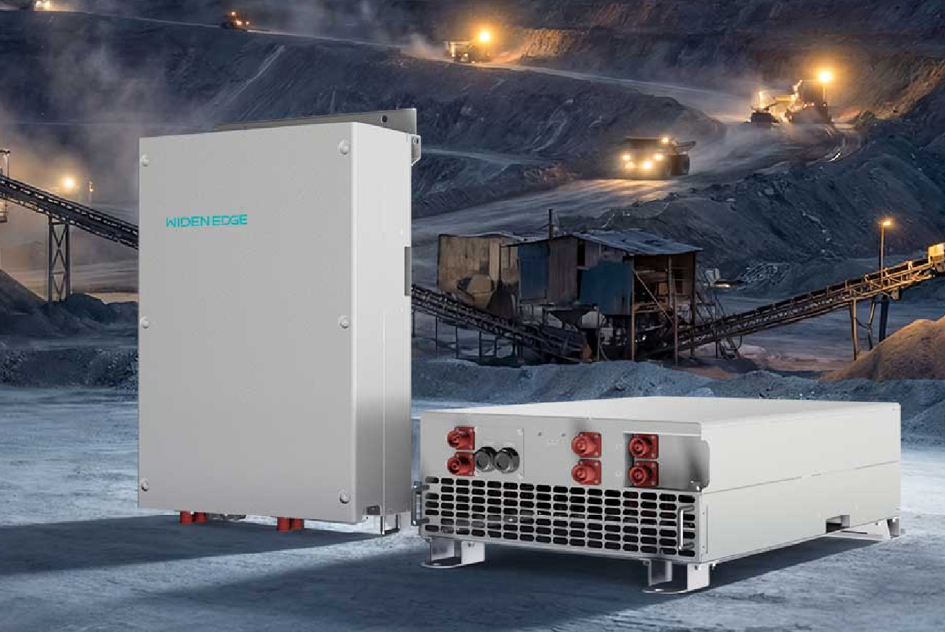
You’re about to put capital and risk into an off-grid storage project — don’t let avoidable protection gaps turn a smart investment into a headline. Start by verifying protection at every layer, and check inverter capabilities early on; for instance, if you’re specifying a 125kW commercial energy storage inverter, confirm its fault isolation, anti-islanding logic, and communication interfaces before rack-up. I’ve reviewed protection schemes on commercial microgrids and debated SiC device behavior at DISTRIBUTECH International, so I know which oversights bite projects during commissioning.
Problem: Faults that stop systems cold
Short circuits, DC arcs, and uncontrolled inverter tripping are the most common causes of unplanned downtime. They look different in off-grid setups: islanding without a stable reference, charge/discharge oscillations, or protective devices coordinating poorly. Miss one coordination point and you’ll have repeated nuisance trips or, worse, hardware damage.
What protection features actually prevent those failures
Prioritize these concrete protections and demand evidence from vendors:- Clear directional overcurrent and ground-fault schemes that account for inverter-fed sources.- Fast DC arc detection with documented sensitivity and response time.- Adaptive frequency and voltage ride-through settings tuned for islanded operation.- Loss-of-reference handling and seamless re-synchronization logic.- Robust communications (Modbus/IEC 61850) with logged events for post-incident analysis.Ask vendors for test reports and waveform captures proving each function under real fault conditions.
How device choice changes the protection game
SiC-based inverters behave differently from silicon IGBT systems: faster switching, tighter control loops, and different thermal/fault profiles. That matters for protection settings and coordination. If your architecture includes a SiC inverter for C&I microgrids, verify manufacturer guidance for protection margins and ensure upstream relays are tested against those rapid transients.
Alternatives and trade-offs to weigh
Two practical approaches show up most often:- Conservative relay-first approach: bulky protection margins, lots of trips, safer short-term but higher downtime.- Coordinated inverter-relay strategy: fewer nuisance trips and better availability, but needs deeper testing and firmware support.Review lab validation reports if you favor coordination. For brownfield retrofits, conservative margins often save time; for greenfield builds, invest in coordination testing to reduce lifecycle O&M costs.
Common deployment mistakes to avoid
Teams routinely miss these:- Accepting default inverter protection profiles without system-level tuning.- Skipping relay-inverter interoperability tests and event logging verification.- Failing to simulate islanding and blackstart sequences under realistic load profiles.- Assuming faster SiC switching eliminates the need for proper DC arc detection.Address these now and you’ll prevent repeated site visits and warranty headaches.
Pre-deployment checklist (fast, actionable)
Use this on-site: verify protective relay curves, confirm inverter anti-islanding and ride-through settings, run coordinated trip tests with recorded waveforms, validate DC arc detectors, confirm communications and timestamp integrity, and document all test evidence. If firmware or settings change, repeat the tests.
Closing synthesis
Protection gaps create predictable failures; systematic auditing prevents them. Match inverter specs to protection needs, require lab-proven test evidence, and insist on coordination between inverters and relays. That practical discipline is exactly the kind of capability WidenEdge brings into project planning and validation, turning specification into dependable on-site performance.